Guides / Process
Grain Flow in Forgings: Why It Matters and How to Check It on a Sample
October 23, 2026
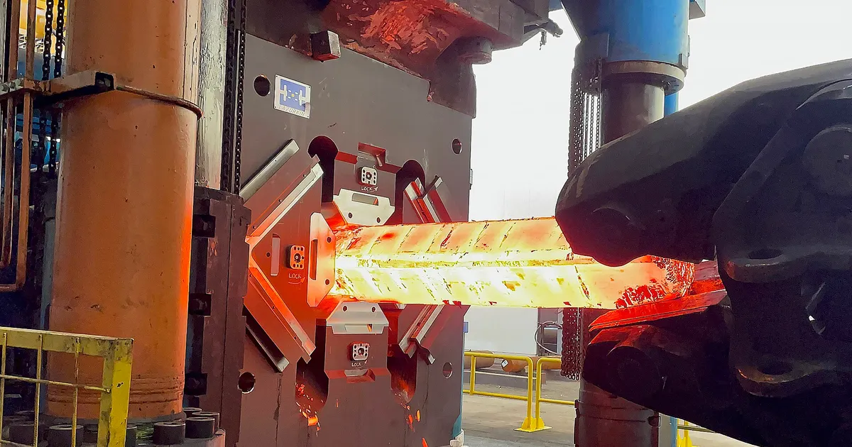
Grain flow is the main reason a forged part usually outlasts a machined or cast part of the same shape and alloy. It is also one of the most misused words in forging sales, so it is worth knowing what it means and how to check it. This guide explains the idea in plain terms, shows how a supplier proves it with a cut-and-etch test and says what to write on an RFQ if grain flow matters for your part.
What grain flow means
Steel and other metals are made of crystals called grains. Inside a billet or bar they also contain small non-metal particles, called inclusions, and areas of slightly different composition from the original casting. When the metal is hot-worked by rolling or forging, these features are stretched in the direction of working, the way the fibres of a rope line up when you pull it. The stretched pattern is the grain flow, also called fibre or flow lines.
In a bar, the flow lines run along the bar. If you machine a part from that bar, the finished shape is cut out of the lines wherever the part has a shoulder, a flange or a change in direction. At those places the lines end at the surface. In a forging, the dies push the metal into shape, so the flow lines bend to follow the contour. A flange is made of lines that turn out into the flange rather than lines that are cut off at its edge.
Why it matters
Metal is stronger and tougher along the flow lines than across them. A wrought steel bar tested along its length shows higher ductility and impact energy than the same bar tested across it. The difference is largest in impact toughness and fatigue strength and smaller in tensile strength. Typical figures show transverse impact energy of about half to three quarters of the longitudinal value, depending on the steel and its cleanliness.
For a part under static load, the effect is modest and a machined part is often fine. For parts under repeated or shock loads, the effect grows. A crankshaft, a connecting rod, a hook, a gear blank and a flanged shaft all have places where stress concentrates, and those places are where cut flow lines would start a crack. Forging aligns the lines with the stress. There is a second benefit, which is that cut ends of flow lines on the surface are the place where corrosion and stress corrosion cracking begin in some alloys. Aluminum grades such as 7075 in the T6 temper are known for this, and a forged shape with flow lines parallel to the surface avoids exposing the end grain.
| Orientation of load to flow lines | Typical behaviour |
|---|---|
| Along the flow lines (longitudinal) | Highest ductility, impact and fatigue strength |
| Across the flow lines (transverse) | Lower ductility, impact and fatigue strength |
| Short transverse, through thickness | Lowest, especially in thick plate and large forgings |
| Flow lines cut at a surface | Starting points for fatigue and stress corrosion cracks |
How forging sets the flow
The die design and the order of operations decide the flow. A closed die part is forged in steps, such as a blocker and then a finisher impression, so the metal flows gradually into the shape and the lines follow the contour. A part forged in one hit from a bar may have the same shape but less well aligned flow. Upset forging turns the lines outward into a head or flange. Our guide to upset forging shows how that works for bolt heads and flanged shafts.
Open die forging works the same way in a coarser form. Drawing out a billet lengthens the lines, upsetting shortens them and spreads them outward. A shaft forged from a billet by drawing out has flow lines along its length, which is the right direction for a shaft. A disc forged by upsetting has lines that radiate outward in the plane of the disc. For the difference between the processes, read open die and closed die forging.
How to check grain flow: the macro-etch test
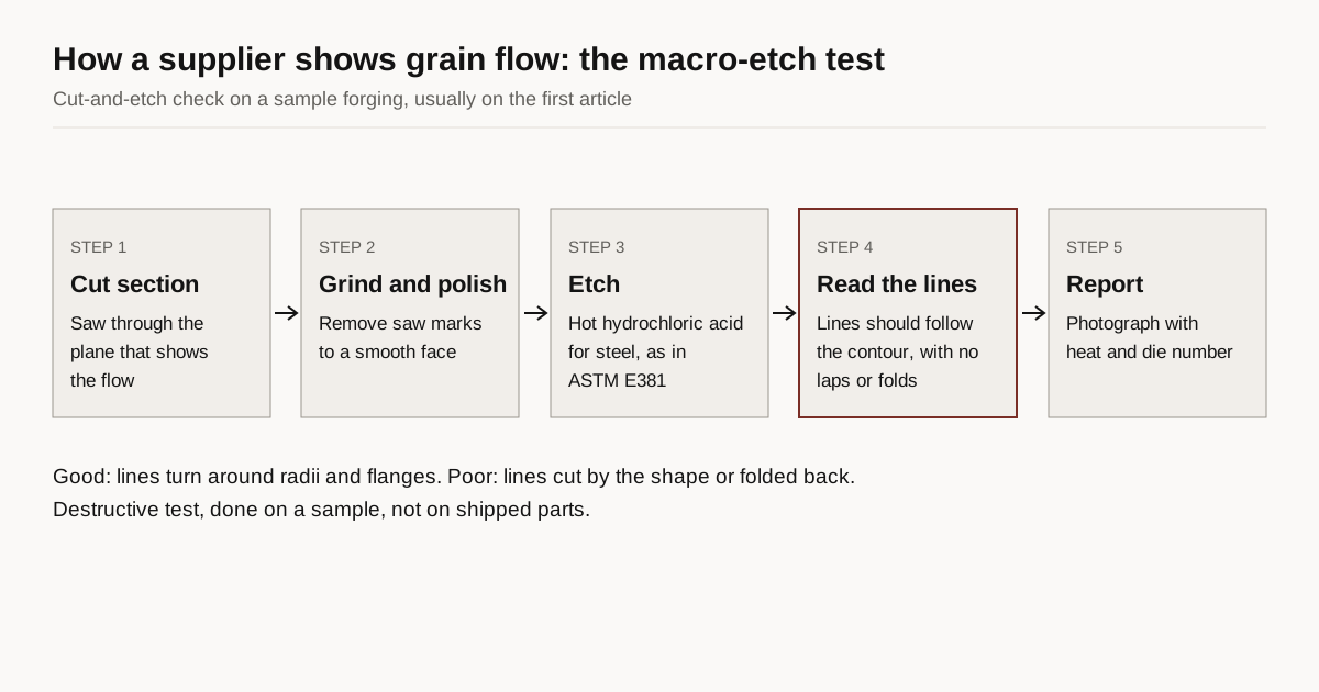
The standard check is a macro-etch of a cut section. The supplier cuts a part or a sample piece through the plane that shows the flow, grinds and polishes the face and etches it in an acid solution. For steel the usual etch is hot hydrochloric acid, as described in ASTM E381, the standard method for macroetch testing steel bars, billets, blooms and forgings. The acid attacks the surface unevenly, so the flow lines show up as visible streaks that can be photographed. Other alloys use different etchants, and the right one is set by the material standard or the supplier’s procedure.
A good etched section shows lines that follow the contour of the part, are continuous around radii and do not stop at the surface in critical areas. A poor one shows lines that are cut across by the shape, folds where the metal has lapped over itself, or dead zones where the metal did not flow at all.
Etching is a destructive test, so it is done on a sample. It tells you about the die design and process, so it is most useful on a first article and again whenever the die or process changes. It also shows other defects, such as porosity and segregation, which is useful for large parts.
Ultrasonic testing and grain flow
Ultrasonic testing does not show grain flow, but the two tests are often used together. The macro-etch shows the direction of the metal flow, while ultrasonic testing finds internal flaws such as porosity and inclusions that the flow lines cannot show. For large forgings both are common. Our guide to ultrasonic testing of forgings explains what that test finds.
Three examples
A crankshaft is the classic case. A forged crankshaft has flow lines that run along the main journals and swing around each crank web, so the lines follow the path of the stress. A crankshaft machined from a straight bar has lines that run straight and are cut off at every web. This is why forged crankshafts are common in engines that run hard, as we describe in the guide to forged crankshafts and camshafts.
A flange on a shaft is the second example. A flange upset from the shaft end has lines that turn out into the flange. A flange cut from a bar that was larger than the flange has lines that run across the flange face, so the fibres end at the rim. For a flange that sees bending or fatigue, that rim is where a crack would start.
A bolt head is the third. A head upset from a bar has lines that wrap around the transition from shank to head, which is the highest stress point in a bolt. A head machined from a larger bar has no such wrap. That is why high strength fasteners are formed, not cut.
Flow defects to know
When the process is not well designed, the flow lines show it. A lap or fold appears when metal folds over itself and traps scale or oxide, and it shows as a line that runs into the part from the surface. A flow-through defect appears when metal flows past a feature of the die and continues across it, which leaves lines that cross the section at an angle. A dead zone appears where metal stays almost still because it contacts a cold die, and it can have a coarser structure than the rest of the part. Each of these can be avoided by good die design and process control, and each is visible in a macro-etch.
Suppliers who know their parts can often tell you what the flow looks like before they cut a die, since they have seen similar parts. If a supplier cannot describe how the flow will run in your part, or never sections a first article, treat that as a warning and ask more questions before you place a large order.
Does grain flow survive machining
Machining removes the surface layer and some of the flow lines go with it. If the forging is near net shape and the machining allowance is small, most of the lines stay intact and still follow the contour. If the forging is oversize and heavily machined, the lines near the surface are cut, and the benefit shrinks. That is one reason closed die forging, which leaves only a light cut, preserves the flow better than open die forging, which leaves a heavy one. It is also why suppliers keep machining allowance as low as the tolerance allows, which brings us back to the drawing. See forging tolerances and draft angles for typical allowances.
When grain flow is worth paying for
Not every part needs a forged flow pattern. Parts with low stress, parts that are only ever loaded in one direction and parts that will be machined from simple shapes are often fine from bar. Our note on forging against casting and machining sets out when to choose each route. Grain flow is worth paying for when the part has any of the following:
- Repeated or shock loads, such as engine, drivetrain and lifting parts.
- Sharp changes in section, such as a shoulder or a flange.
- A thin web or a long arm that carries bending.
- A safety role, where a failure would harm people or equipment.
- A corrosion-sensitive alloy where cut end grain would be exposed.
What to write on the drawing
If you need grain flow, say so in terms that can be checked. Words like “forged for grain flow” are weak. Better is a note that requires grain flow to follow the part contour in the plane shown, with a macro-etch on the first article and on any change of die. Name the etch standard, and ask for a photograph with the report. If you have a reference part, send a picture of it. If you only want to confirm that the forging is sound, a note on ultrasonic testing is usually the better tool.
What to put in the RFQ
Include the drawing with the critical stress areas marked, the material and specification, the yearly quantity and the testing you expect. State whether you need a macro-etch on the first article and how many sections. If you are comparing a forged route with a machined route, say so and ask suppliers to quote both so you can see what the flow lines are worth.
Next step
Send an RFQ with your drawing. We match you with up to 3 forging suppliers that make this kind of part, and we reply within 24 business hours. For the full checklist of questions, read how to choose a forging supplier.
Grain flow follows the process that shapes the part; see the processes side by side in our guide to types of forging.
Frequently asked questions
Is grain flow the same as grain size?
No. Grain size is how large the individual crystals are. Grain flow is the direction in which the metal structure and its inclusions are stretched. A part can have a fine grain size and poor grain flow, or the reverse. Forging controls both, but they are checked in different ways.
Does every forging have good grain flow?
No. Forging gives the chance for good grain flow, but the die design and the sequence of operations decide whether the flow follows the part. A poorly designed forging can have flow lines that cut across the shape or fold back on themselves.
Can I check grain flow without destroying the part?
Not directly. The standard method is to cut a section from a sample part, polish it and etch it. Most buyers ask for this on the first article, and then again only if the die or process changes.
Need a quote for this part?
Send the drawing. We match you with up to 3 forging suppliers and reply within 24 business hours.
Send my RFQ