Guides / Specifications
Ultrasonic Testing of Forgings: ASTM A388 and What It Finds
October 30, 2026
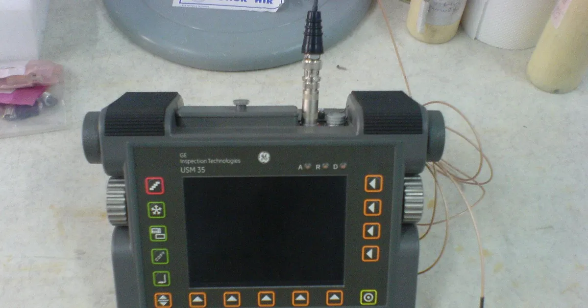
Ultrasonic testing, or UT, is how forging buyers confirm that a part is sound inside. It is common on shafts, rings, discs, pressure vessel parts and other forgings that carry load or pressure and cannot be inspected by cutting them open. The test is quick to describe, but the paperwork around it trips up many first-time buyers. This guide explains what UT finds, what ASTM A388 and similar standards cover, what acceptance limits mean and how to write the test into an RFQ.
How ultrasonic testing works
A probe held against the surface sends a short burst of high frequency sound into the metal. Sound travels through sound metal and reflects from the far wall of the part, which the instrument shows as a back-wall echo. If there is a flaw such as a void or a crack in the path, part of the sound reflects from it earlier. The instrument shows that as an extra echo, and the time it takes to return shows how deep the flaw is. A flaw that is large enough can also weaken or remove the back-wall echo.
The tester scans the surface in a pattern, usually with a straight beam probe that sends sound at right angles to the surface. For rings and hollow forgings, angle beam probes send sound at a slant so that it can find flaws that are oriented to the surface. Probe frequencies of about 1 to 5 MHz are typical for steel forgings, with 2.25 MHz common. Lower frequencies travel farther and see through coarse grain, and higher frequencies find smaller flaws near the probe.
What UT finds
UT is good at finding flaws that lie inside the metal:
- Shrinkage cavities and porosity left from the ingot.
- Non-metallic inclusions in clusters.
- Internal cracks, bursts and flakes, which are small cracks caused by hydrogen.
- Laminations in forgings made from flat material.
- Lack of bonding in forged and welded composite parts.
It does not find everything. Flaws very close to the surface lie in a zone where the probe cannot separate the sound pulse from the flaw echo, so the near surface is covered by other tests. Flaws that are parallel to the sound beam can be missed. Coarse grain in some stainless steels and nickel alloys scatters the sound and makes the test less sensitive, so these use a special procedure. Our guide to stainless steel forgings covers why.
What ASTM A388 covers
ASTM A388 is the standard practice for ultrasonic examination of steel forgings. It sets out how the test is carried out, not what is acceptable. It covers the equipment, the condition of the surface, the calibration of the instrument and the way indications are recorded. It is written mainly for heavy forgings and applies to straight beam and angle beam testing. A related standard, ASTM A745, covers austenitic steel forgings, where coarse grain needs a different method.
Key points that matter to a buyer:
- The surface must be machined smooth, usually about 6 micrometres Ra, so that the probe couples well.
- The instrument is calibrated either on a reference block with flat bottom holes or with a method that relates echo height to flaw size and distance.
- Indications are recorded when they exceed a set reference level, when the back-wall echo drops by a set amount or when a flaw seems to move across the part.
- The test report records the equipment, the probe, the reference and the results.
In Europe, EN 10228-3 covers ultrasonic testing of ferritic and martensitic steel forgings and EN 10228-4 covers austenitic and duplex stainless steels. They use quality classes from 1 to 4, where a higher class has tighter limits. Our note on forging certifications and specs covers how these fit into a purchase order.
Acceptance limits
A388 and EN 10228 describe how to find and size a flaw. The limit is a separate document. For pressure parts, the limit often comes from the design code or the product specification. For other parts, it is set by the customer drawing or an agreed note. Typical wording sets a maximum allowed echo amplitude from a flaw of a certain size at a certain depth, forbids any indication that exceeds a reference amount and forbids a loss of back-wall echo above a set percentage.
| Quality class (EN 10228-3 style) | Meaning | Typical use |
|---|---|---|
| Class 1 | Loosest limit, large flaws allowed | General engineering parts |
| Class 2 | Moderate limit | Machinery shafts and rings |
| Class 3 | Tight limit | Pressure and rotating parts |
| Class 4 | Tightest limit | Critical rotating parts, turbine and nuclear |
Check the exact limits in the edition you cite, because they differ by wall thickness and by flaw type. A buyer who writes “UT to ASTM A388” without a limit has not given the supplier anything to accept or reject against.
Calibration methods in plain terms
Two calibration methods appear in most procedures, and a buyer does not need to master either one, but it helps to know that they exist. The first uses a reference block with flat-bottom holes of known size at known depths. The tester sets the instrument so that a hole of a given size gives an echo of a set height, and then draws a curve of echo height against depth, called a distance amplitude correction curve. A flaw echo that rises above the curve is recorded. The second method uses calculated curves that relate echo height to flaw size and distance for the probe in use, known as the distance gain size method. It is common in Europe and suits large forgings where a reference block of the same shape would be impractical.
Both methods report flaw size as an equivalent flat-bottom hole, which is a reference, not the real flaw size. A real flaw such as a crack or a cluster of inclusions reflects sound differently from a smooth flat hole, so the equivalent size is only a guide. That is why acceptance limits are written in terms of the reference rather than in millimetres of crack.
Cost and lead time
Ultrasonic testing adds cost for the operator time, the machining needed for a good test surface and, on large parts, the handling. For small forgings tested in batches the cost per piece is low. For a large ring or shaft tested over the full volume with several probes, it can take hours and a surface machined to size before the test. If the test needs a second pass after a repair or after reheat treatment, the cost and the time increase.
Lead time is more affected by sequence than by test time. A part that must be rough machined, heat treated, tested, finish machined and tested again passes through the shop several times. If you can accept a single test after rough machining, you shorten the route. If your specification needs a test after final machining, tell the supplier early so the schedule includes it.
Heavy sections and reduction ratio
In heavy sections the main internal risk comes from the ingot, where shrinkage and segregation concentrate toward the centre. Forging closes these spaces and breaks up the structure, but only if the forging is reduced enough. Reduction ratio is the ratio of the starting cross-section to the finished cross-section, and many specifications require a minimum, often 3 to 1 or more for ingot-based forgings. Ask what reduction ratio the supplier will use, because a part made from a billet that is only slightly larger than the finished size may not have closed the centre, and a UT test can then find the flaws that proper reduction would have removed. We did not find the 3 to 1 figure above in a standard we read; for what the sources we opened say about minimum ratios, see forging reduction ratio.
UT, magnetic particle, penetrant and radiography
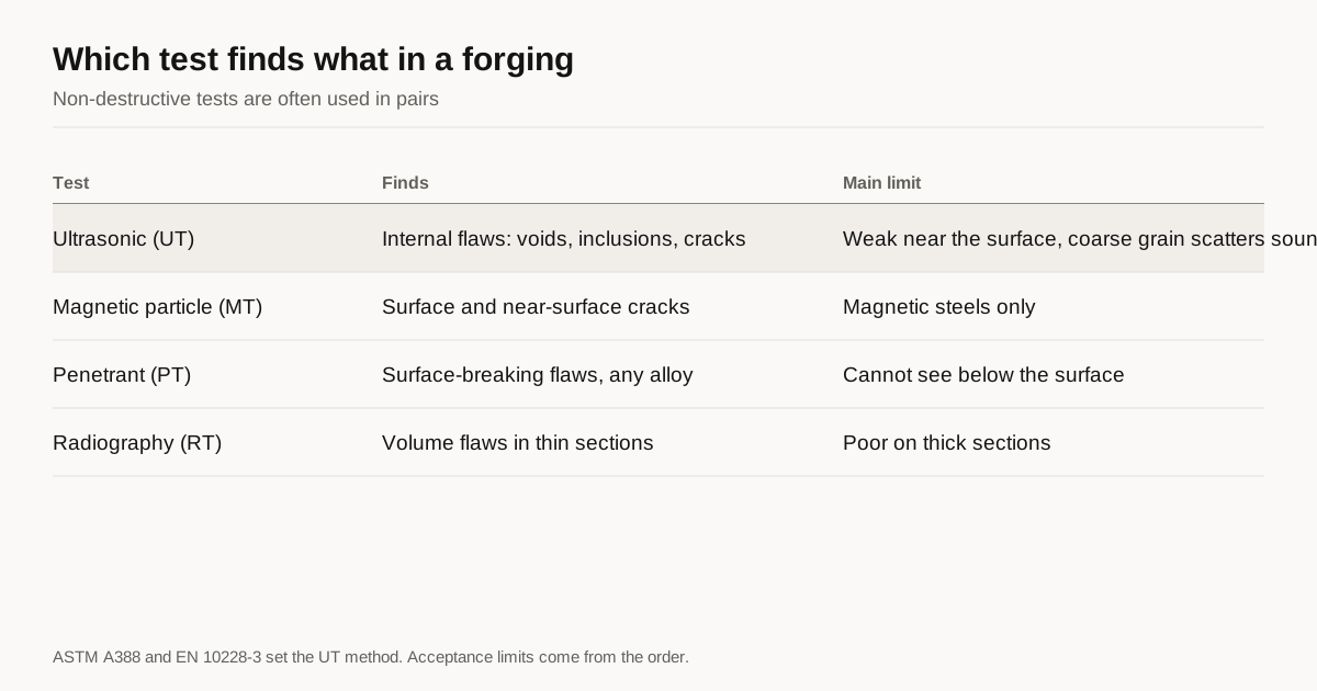
UT is one of several non-destructive tests. They find different things, so most critical forgings need more than one.
| Test | Finds | Limits |
|---|---|---|
| Ultrasonic (UT) | Internal flaws | Poor on the near surface and on coarse grain |
| Magnetic particle (MT) | Surface and near-surface cracks in ferritic steel | Needs a magnetic material |
| Penetrant (PT) | Surface-breaking flaws in any alloy | Cannot see below the surface |
| Radiography (RT) | Volumetric flaws in thin sections | Poor on thick sections, safety controls needed |
For steel forgings UT with MT is the usual pair. For stainless steel and nickel alloys, UT with PT is the common pairing.
When UT is done
UT is normally done after the last heat treatment that sets the structure, because that treatment can change how the metal reflects sound and because it may open flaws. It is done before holes, grooves and keyways are machined where possible, because those features block or scatter the beam. If the part must be heat treated again after UT, for example because of a repair, the test is repeated. For large rings, UT may be done at several stages. Our guide to heat treatment of forgings explains why order matters.
Operators and reports
The test is only as good as the operator and the procedure. Ask what qualification the operators hold. Common schemes are ISO 9712 and SNT-TC-1A or CP-189 in the United States. These are personal qualifications, not company approvals, so ask for the level and the scheme on the report. The written procedure should be on file and referred to by number on the report.
A UT report should include the part number, heat number and drawing revision, the standard and the quality class, the instrument and probe, the reference block or calibration method, the surfaces scanned, the result and the operator. Ask for the report with the shipment, not as an extra on request.
Common reasons for rejection
Forgings are rejected in UT for a few reasons. Shrinkage or porosity in the centre of a large forging that was not reduced enough. Inclusion clusters from poor steel cleanliness. Hydrogen flakes in a heavy section that was not given a slow enough cool. Burst cracks from forging too cold or with too heavy a bite. Suppliers prevent these with good steel, enough reduction ratio and controlled cooling, so a supplier who tests heavy forgings regularly should be able to tell you how they prevent each one.
What to put in the RFQ
Write the test, the standard, the edition, the quality class or limit, the stage of the process, the operator qualification and the report you need. Add magnetic particle or penetrant testing if you need surface tests too. State which surfaces will be machined for testing and whether you will accept rejection and replacement at the supplier’s cost.
Next step
Send an RFQ with the drawing and the test requirement. We match you with up to 3 forging suppliers who regularly deliver UT-tested forgings, and we reply within 24 business hours. For a wider look at what to check, read how to choose a forging supplier.
See also: forged shafts and axles, the reference page on routes, steels and inspection.
See also: acceptance levels for UT, MT and PT on forgings under EN 10228.
Frequently asked questions
Does ASTM A388 give the acceptance limits?
No. ASTM A388 describes how to carry out the test and how to calibrate and record indications. The acceptance limits come from the product specification or the purchase order, for example a quality class in a pressure vessel specification or a customer drawing note.
When in the process is UT done on a forging?
Usually after the final heat treatment that sets the structure, and before holes, grooves or other features are machined that would block the sound path. The forging is machined to a smooth surface so the probe makes good contact.
Can ultrasonic testing find surface cracks?
Not reliably. It is designed for internal flaws. Surface and near-surface flaws are found with magnetic particle inspection for ferritic steels or penetrant inspection for other alloys. Many forging orders call for both UT and a surface test.
Need a quote for this part?
Send the drawing. We match you with up to 3 forging suppliers and reply within 24 business hours.
Send my RFQ